One of my tasks as an engineering education developer at BU is to beef up the content of some activities with some higher level concepts. Recently I've been working on an activity where students get to design, build, and test their own wind turbines. Right now the activity works great with middle school students, but we want to improve the activity and make it more challenging so that we can bring it to high schools as well. The activity uses store bought wind turbine kits with a variety of blade types. Students can choose the material of the blades, the size of the blades, how many blades, and how to angle the blades. Then, once they've built their turbine, it's placed in front of a box fan and connected to a volt meter to measure the power. After their first design, students are allowed to make changes and test a second time before the teacher gathers everyone for a recap.
Our goal is to enable students to use data obtained from their first test to quantitatively evaluate and improve the performance of their design. This requires some type of quantitative analysis of the wind turbine. So I began doing some math. I just finished a course in aerodynamics, where we learned all about airfoils and wings, so I felt I had a good handle on the concepts at hand. After all, a wind turbine is just a bunch of rotating wings, right?
Well regardless, that's how I modeled it. But unlike regular airplane wings, rotating wings (aka blades) don't all feel the same wind. The ends of the blades travel much faster than the inward portions, meaning the airspeed for that section of blade is faster. So the normal approach doesn't work in this case, because the wind is quite different everywhere across the wing.
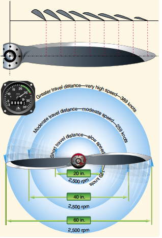
This image shows how much the actual speed of the blade varies with distance from the hub. Image Credit: http://www.cfinotebook.net/notebook/operation-of-aircraft-systems/propeller.php
So what can be done to solve the problem? Well when engineers come across a problem like this, they usually try to reduce it to something they already know how to solve. To give an example of how this is done, imagine taking a thin slice of the blade. Because it is so thin, the wind speed on one end is almost the same as the wind speed on the other end. Because the wind speed is *essentially* the same all across this tiny wing, we can use our original method on this tiny wing and get a good approximation. And it turns out if you add up an infinitely large number of infinitely thin blades, you can actually end up with a complete, finite blade; and no error! This technique of adding radial sections of the blade is called the Blade Element Method (BEM).
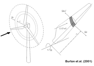
Here is a picture showing the 'slice' of the blade. Image Credit: http://fessrg.ucsd.edu/Research/Wind/
BEM seems to be pretty widely used for getting preliminary performance estimates when designing a new propeller, helicopter rotor, wind turbine, or really anything else that has rotating wings. However there are limitations. The most significant limitation is that BEM cannot account for any radial flow - that is, if there is air moving along the blade from one tiny wing to the next. When engineers are satisfied with results from preliminary estimates such as BEM, they may move on to more accurate and sophisticated methods like a numerical simulation. But for my purpose, I think BEM is just fine.